ALU Primer
The Arithmetic Logic Unit (ALU) is a combinational circuit which performs arithmetic, logic, and bitwise operations on binary numbers; and it is an indispensable component within a CPU!
Arithmetic Operations
Generally, an ALU can inherently perform addition and subtraction only combinationally. While it has the capacity for multiplication and division, these operations in basic ALUs are often achieved through repeated cycles of addition and subtraction. For instance, in multiplication, a common method involves adding and shifting bits, which can be time-consuming. One benefit of this repetitive method is its minimal hardware requirement, a factor that presents a trade-off between speed and space/components conservation. Such a trade-off can be acceptable, as the saved space can be repurposed for other functionalities, whether on a silicon chip or a PCB. However, modern CPUs often include more advanced ALUs with dedicated hardware for multiplication, expediting these operations significantly beyond the basic repeated addition approach. In the same vein, division, though often more complex, can be optimized using specialized methods that go beyond repetitive subtraction.
Logical Operations
Logical operations (AND, OR, NOT etc…) are used for making logical comparisons and decisions in various computing tasks, making them essential in the overall processing of data.
Bit-Shifting Operations
The ALU can shift bits either to the right or the left, which is useful not only for multiplication and division of binary numbers but also for efficient bit manipulation and implementation of certain arithmetic operations.
The SAP-1 being an introductory architecture contains an ALU only capable of addition and subtraction. These two operations however, are enough to theoretically perform any calculation given enough time and memory.
In addition to arithmetic operations, my ALU can handle logical shift {Left Shift (LSL), Right Shift(LSR)}, and logical Boolean operations (AND, OR, and XOR). These extra capabilities make it more versatile for a variety of tasks.
Logical operations are straightforward, as they’re direct outputs of their respective gates.
For instance, “ANDing” two 4-bit words is just a matter of inputting them into an 8-bit AND gate. And bitwise “ANDing” the bits of two 4-bit words is the same as inputting each pair of bits from both words into four two-input AND gates, and consider the output of all of the gates as the 4-bit word result.
Arithmetic and shift operations on the other hand are more interesting hardware-wise.
Arithmetic Operations
Addition (ADD)
Binary addition is very similar to decimal addition. For example:
(10) +  (5) = (15)
1010 + 0101 = 1111

carry           0000
Number A        1010
Number B      + 0101
               ------
                1111
The process is as direct as adding up each corresponding pair of bits, and if the sum is 2 (10 in binary) or more, you carry over a bit to the next left column.
For example:
 (9) +  (7) = (16)
1001 + 0111 = 10000

carry         01110
Number A       1001
Number B     + 0111
              ------
              10000
In the example above, a carry is generated because the sum of the rightmost bits is 10 in binary, or 2 in decimal. The 0 is placed in the result, and the 1 is carried over to the next column. The same happens for the second column from the right, and so forth.
In the final operation(Fourth column from the right), a 1 is carried outside the 4-bit range in the result row. Consequently, the ALU’s Carry Flag (C) is set to 1, indicating that a carry has occurred.
The carry flag becomes particularly relevant in multi-precision arithmetic, where operations involve numbers that are too large to be accommodated within the standard bit-size of the ALU.
With this basic addition refresher out of the way, let’s look at how the CPU manages this task internally. To perform additions, the ALU uses a circuit called a “Full Adder”. We’ll see how it works, but before, let’s take a look at its building block, the “Half Adder”.
Half Adder
A half adder is a type of binary adder that operates on two binary digits and produces two outputs: the sum and the carry. It is referred to as “half” because it does not account for any carry input from previous operations(Which is needed in a multi-bit addition), making it somewhat limited.
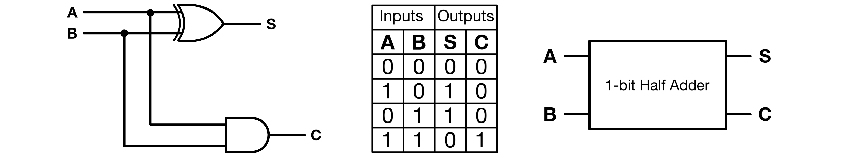
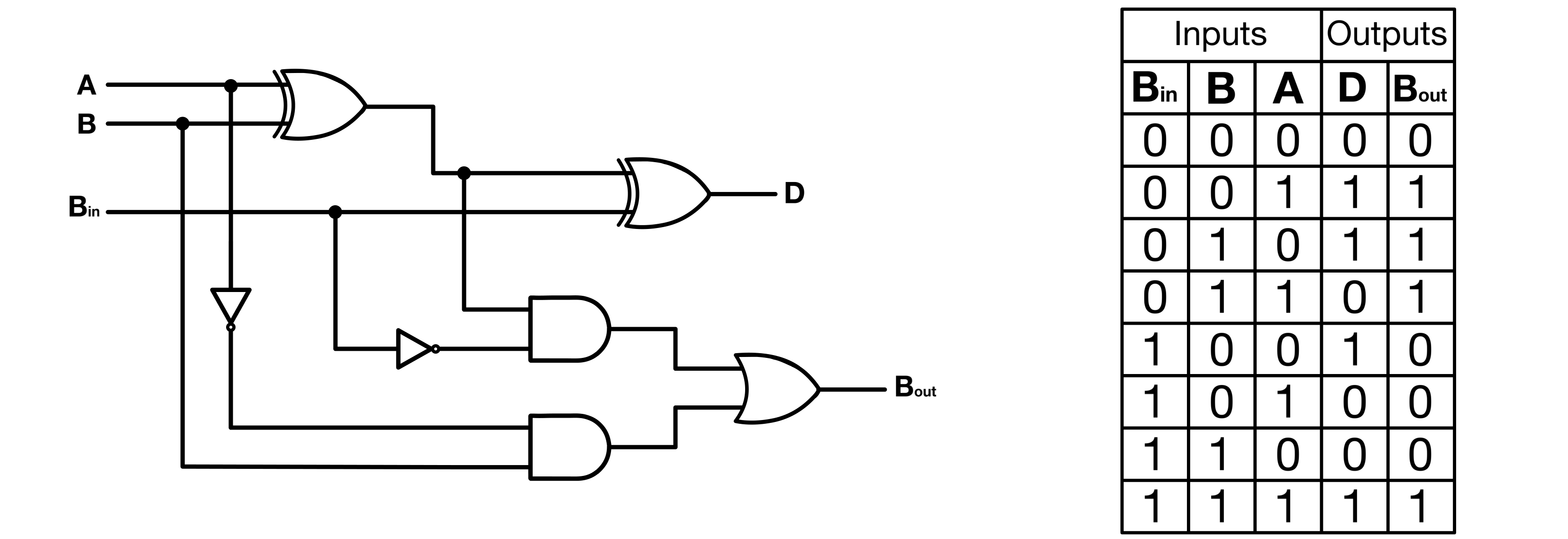
In this circuit, the sum is derived from the XOR gate’s output, while the AND gate’s output determines the carry.
Full Adder
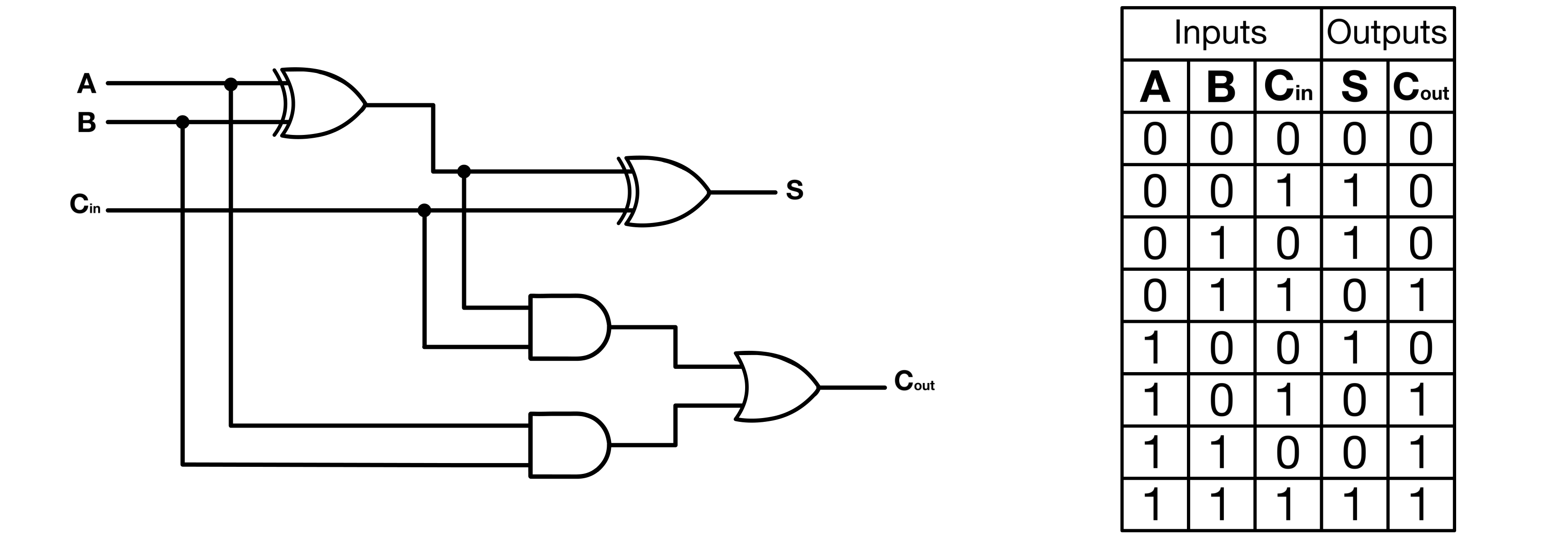
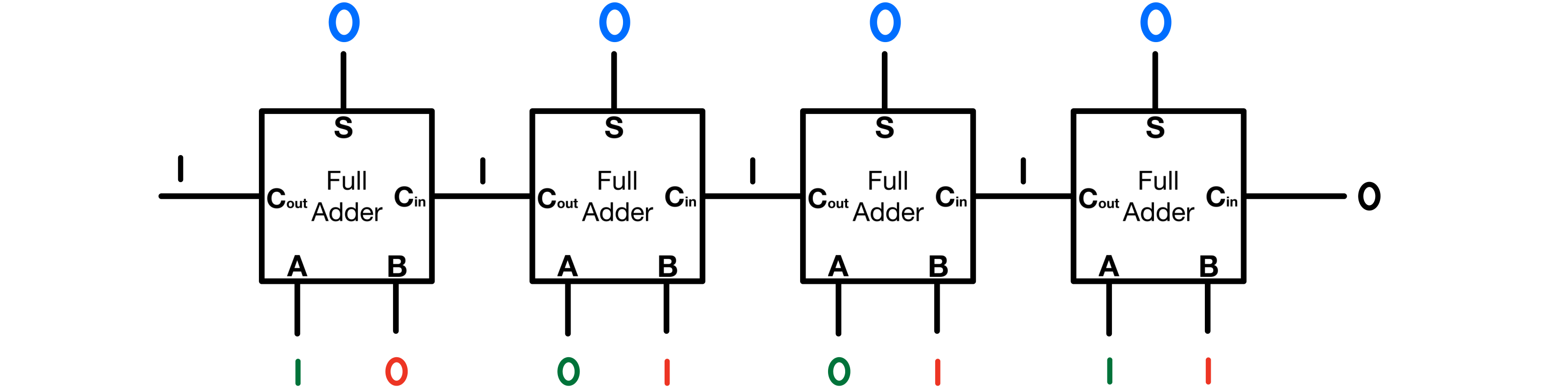
A full adder is an enhanced version of the half adder, capable of handling the addition of three bits: two input bits and a carry bit resulting from a previous calculation. This additional feature makes it more versatile and complete, as it overcomes the limitations of the half adder which cannot process carry inputs from preceding additions.
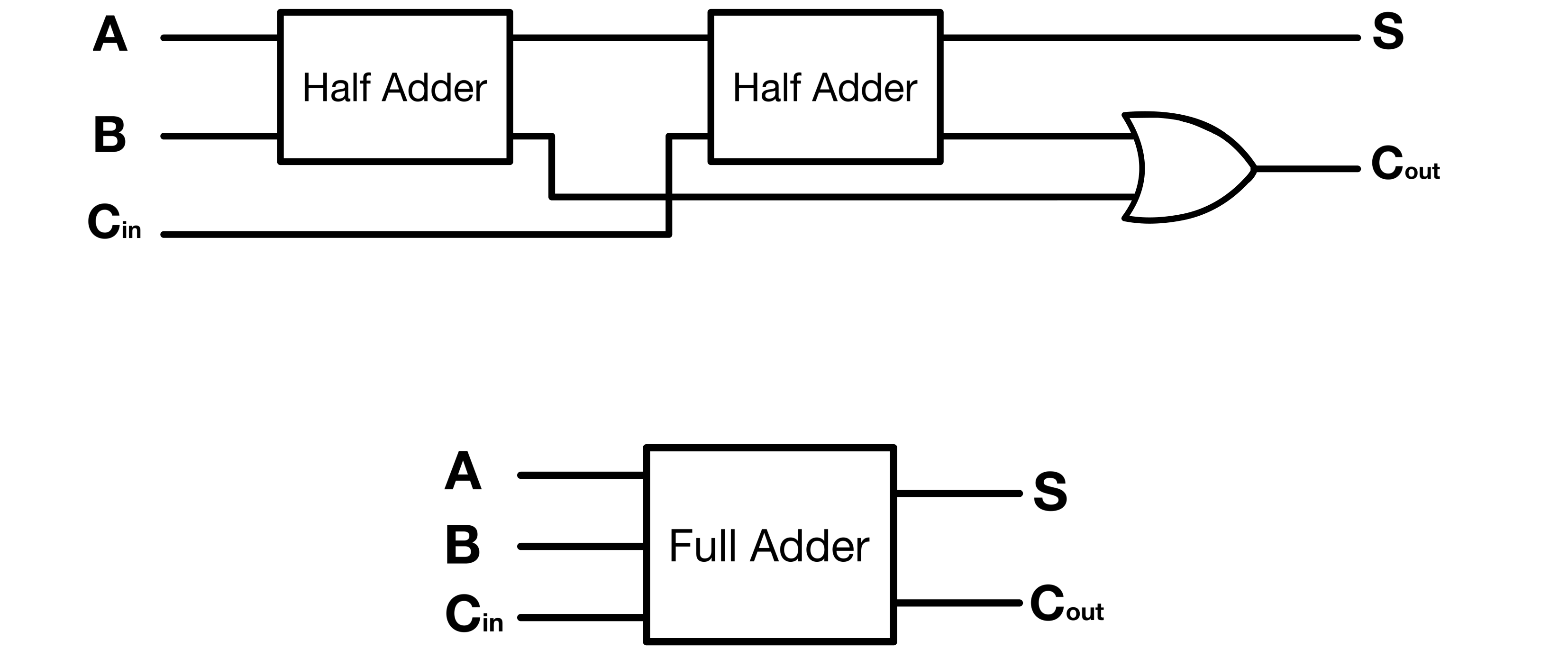
In practice, a full adder can be constructed by combining two half adders. One half adder is responsible for adding the two input bits, while the other accepts the carry from the first half adder to provide the final sum.
Going back to the two previous addition examples; a full adder would handle them as follows:
(10) + (5) = (15)
1010 + 0101 = 1111
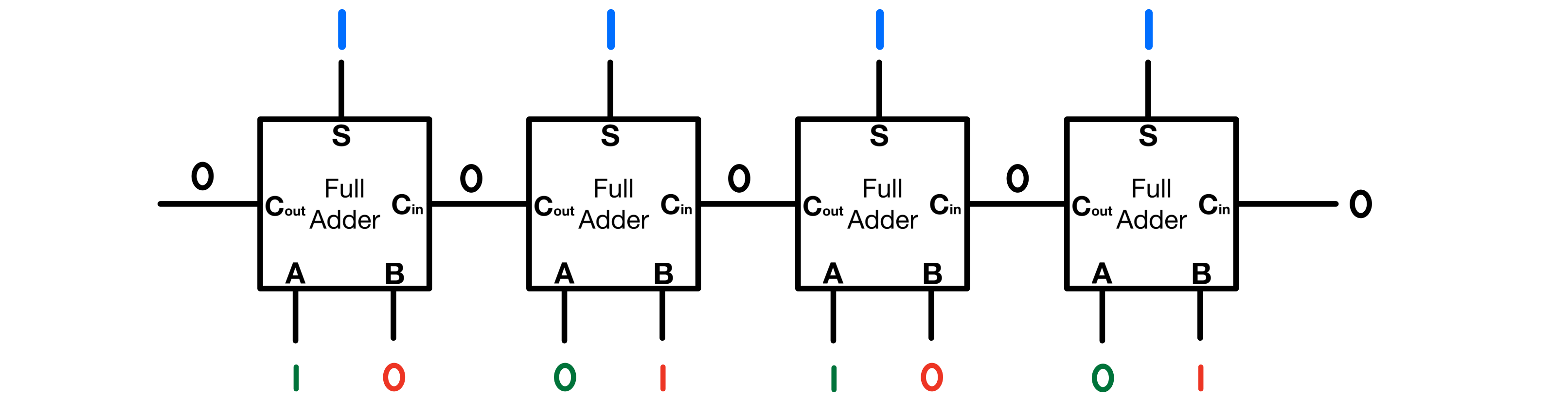
And
(9) + (7) = (16)
1001 + 0111 = (1)0000
Subtraction (SUB)
Subtraction can be a bit more complex than addition. At its core, the representation of a number, whether in decimal, binary, or hex, serves as an abstraction of an actual quantity. For instance, representing four apples in words can be done as “4 apples”, “0b100 apples”, or “0x4 apples”. Regardless of how we represent/write it, in reality, we still refer to 🍏🍏🍏🍏.
As mentioned in the Basic Definitions And References, Binary is the language of computers, not necessarily because it is the best numerical system, but because it mirrors the inherent ON/OFF nature of transistors, the fundamental components of digital electronics.
Computers “speak” binary because their basic hardware operates in binary.
When dealing with the concept of negative numbers, we’re adding another layer of abstraction. One way to think about negative numbers is as the “absence of a quantity”(I can imagine math and philosophy enthusiasts facepalming at this definition, but hopefully it makes enough sense). The challenge then becomes: How do we represent this added abstraction to a mindless electronic circuit?
There are typically three major ways to represent negative numbers in binary: sign-magnitude, one’s complement, and two’s complement. In all three systems, the leftmost bit is the sign bit, 0 for positive numbers and 1 for negative numbers.
| Decimal | Signed Magnitude | Signed One’s Complement | Signed Two’s Complement |
|---|---|---|---|
| +7 | 0111 | 0111 | 0111 |
| +6 | 0110 | 0110 | 0110 |
| +5 | 0101 | 0101 | 0101 |
| +4 | 0100 | 0100 | 0100 |
| +3 | 0011 | 0011 | 0011 |
| +2 | 0010 | 0010 | 0010 |
| +1 | 0001 | 0001 | 0001 |
| 0 | 0000 | 0000 | 0000 |
| -0 | 1000 | 1111 | - |
| -1 | 1001 | 1110 | 1111 |
| -2 | 1010 | 1101 | 1110 |
| -3 | 1011 | 1100 | 1101 |
| -4 | 1100 | 1011 | 1100 |
| -5 | 1101 | 1010 | 1011 |
| -6 | 1110 | 1001 | 1010 |
| -7 | 1111 | 1000 | 1001 |
Table 1: Decimal, Sign-magnitude, One’s complement, and Two’s complement Representation of 4-bit Signed Binary Numbers
Sign-Magnitude
In the sign-magnitude system, the remaining bits represent the magnitude of the number. So, 0101 would represent +5, and 1101 would represent -5. It is straightforward but has a significant drawback: there are two representations of zero, 0000 and 1000, which can complicate calculations.
One’s Complement
Then there’s one’s complement. It flips all the bits of a positive number to get the negative equivalent. But like sign-magnitude, one’s complement also has positive and negative zeros, which can be problematic.
Two’s Complement
This brings us to the two’s complement system, the most widely used. It not only solves the negative zero issue but also makes arithmetic operations align seamlessly. With two’s complement, you flip the bits and add 1 to get the negative of a number. The reason as to why this works might not seem intuitive at all(At least it was not to me when I was first learning about binary). This process is very straightforward hardware-wise as it can be achieved by minimally modifying the adder circuitry.
I think the “Why Inversion and Adding One Works” chapter of this article does a great job at explaining the mathematical intuition behind complements.
Reminder: minuend - subtrahend = difference
Again, with two’s complement, you simply flip the bits of the subtrahend and add 1 to it, to get the negative representation of a number. And it just now becomes a matter of adding the transformed number to the minuend. This is exactly what the binary subtractor does.
Full Subtractor
The full subtractor is another fundamental binary arithmetic circuit that is designed to execute binary subtractions. It takes two binary digits and a borrow from the previous subtraction, yielding a difference and a borrow output.
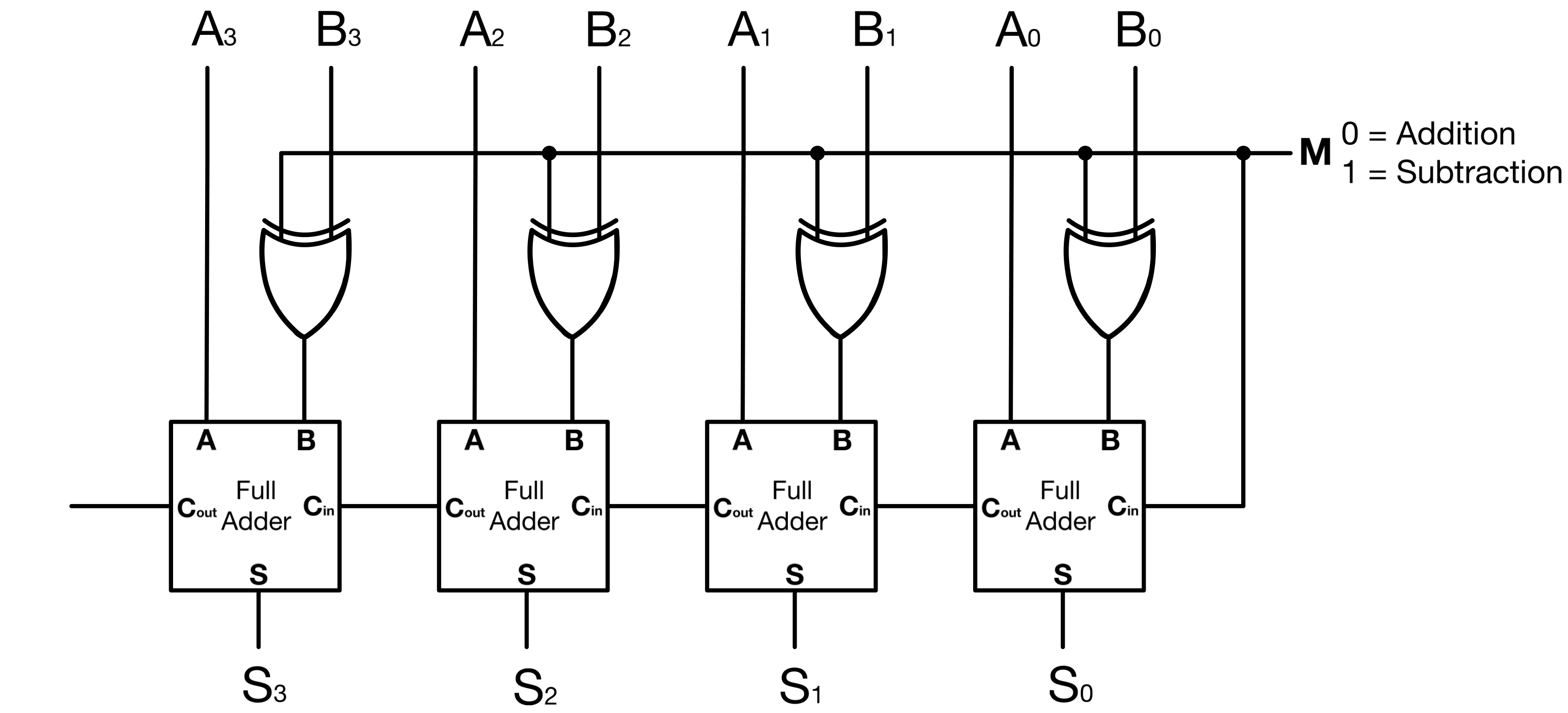
This circuit serves as a subtractor when M = 1 and as an adder when M = 0. The subtractor takes the 2’s complement of B(By first reversing all bits and adding M = 1), and adds it to A. Only a XOR gate is added to each bit of an Adder’s second input to convert it to a Subtractor.
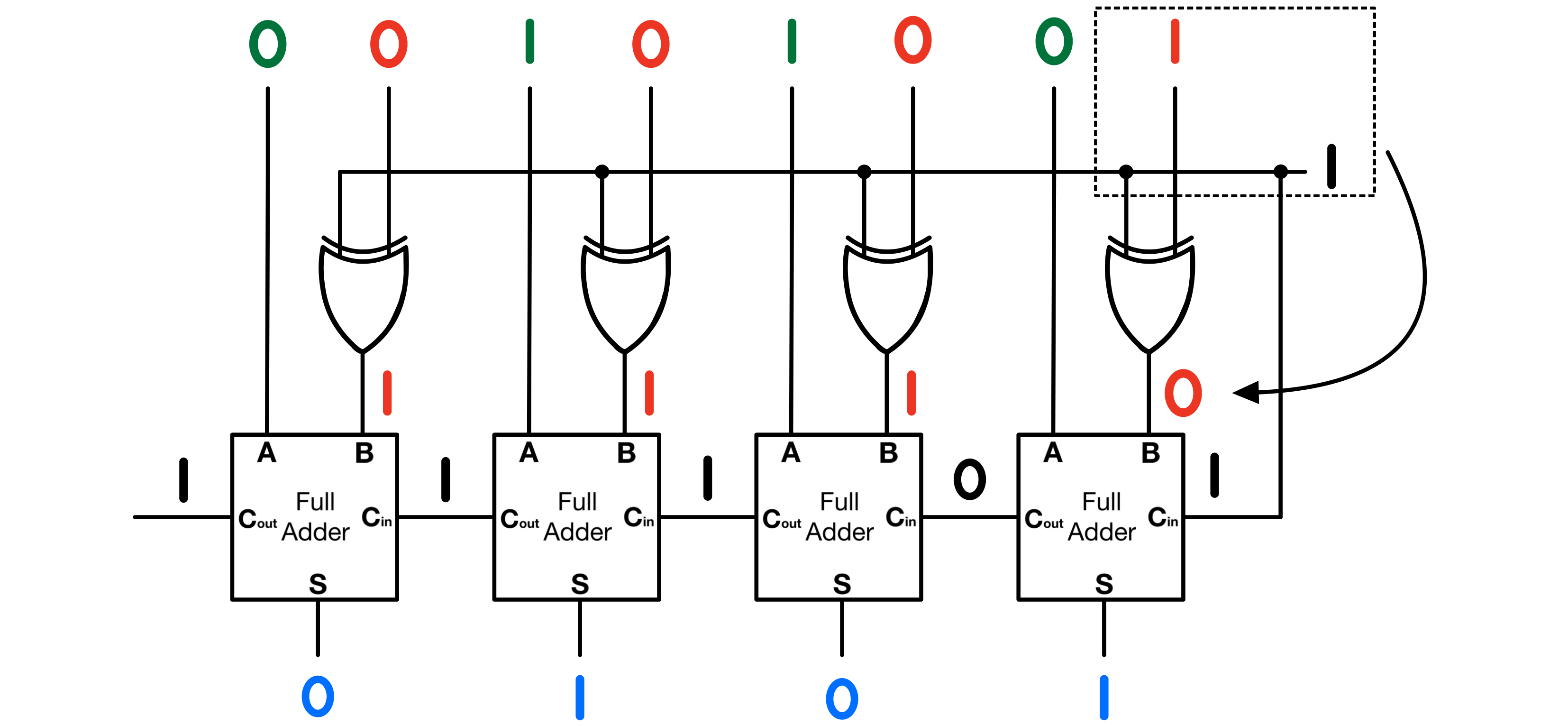
Two’s Complements Using Full Subtractor
For the sake of simplicity, let’s consider a 4-bit ALU subtracting 0001(1) from 0110(6). First let’s compute the subtraction “by hand”:
(6)  - (1) =  (5)
0110 - 0001 = 0101

borrow          0001
Number A        0110
Number B      - 0001
               ------
                0101
The answer just makes sense because we understand the meaning of the minus sign; but so far our hardware can only do addition. Subtracting a positive number B, from any other number A (A-B) is the same as adding (-B) to A ( A + (-B)). Two complements make it so that, technically we never “subtract a positive number from”, but always “add a negative number to”.
Going with the example above:
(6)  -  (1) =  (5)
0110 - 0001 = 0101
First, lets convert both unsigned numbers to their two’s complement:
6 is 0110 and 1 is 0001.
The Signed Magnitude representation of +6 is similar to its Two’s Complement representation.
To get -1, first we get the one’s complement of 1 (flip all bits):
1110
and add 1
1110
+  1
-----
1111
Now in two’s complement,
(6) - (1) (6) + (-1)
0110 - 0001 becomes: 0110 + 1111
carry      11101
(6)         0110
(-1)      + 1111
           ------
            0101
0110 - 0001 = 0101
The result is the same as a “normal” subtraction, the difference here is the subtraction process in this case can easily be implemented in hardware.
Shift Operations
Shift operations in an ALU simply move bits to the left or right in a binary number. They are often used for multiplication and division and can help to adjust the value of a binary number or change its structure for other logical operations.
Left Shift (Logical Shift Left - LSL)
A left shift operation moves all bits in a binary number a certain number of places to the left. Empty positions on the right are filled with zeros. Each left shift effectively multiplies the binary number by 2.
Example: Original: 0101 (5) Left Shift: 1010 (10)
Right Shift (Logical Shift Right - LSR)
A right shift does the opposite, moving all bits a certain number of places to the right. Empty positions on the left are typically filled with zeros, halving the value of the binary number for each position shifted.
Example: Original: 1010 (10) Right Shift: 0101 (5)
Arithmetic Shifts
Arithmetic shifts are used with signed binary numbers. When performing an arithmetic right shift, the empty positions on the left are filled with the value of the sign bit to keep the sign of the number the same. An arithmetic left shift is similar to logical left shift.
Rotate
Rotate operations shift bits around to the other side of the binary number when they fall off one end. It can be to the left or right. For example, with a rotate right operation, a bit that falls off the right end will reappear on the left.
Example for Rotate Right: Original: 1011 (11) Rotate Right: 1101 (13)
«««««««««« Previous Post: Bus and General Purpose Registers
Next Post: ALU & Flags »»»»»»»»»»
Updated: