
 Clock
Clock
 Memory
 Control
OLED Display
BASICS PRIMER
Unlike traditional LCD (Liquid Crystal Displays), which rely on a uniform backlight, each pixel in an OLED (Organic Light-Emitting Diode) display emits its own light. This makes color contrasts look very vibrant. Typically, LCDs used for minimal projects, such as the HD44780 based LCD2004, have convenient built-in features such as "auto increment after read/write". On these LCDs, characters and symbols can be placed at pre-encoded dot-matrix blocks within the display.
On the other hand, similarly-sized OLED displays are controlled on a pixel basis. While this offers more control over each pixel, it also introduces greater complexity in programming and control as each pixel must be addressed and manipulated independently, which can be more challenging and time-consuming.
I use the Adafruit 2.7” Monochrome 128x64 OLED display module. It has both SPI and 8-bit parallel modes (6800 and 8080). Since my build is relatively slow (at least compared to commercial MCUs), I use the parallel mode; 6800 specifically since it’s simpler and more common than 8080. The display is driven by the Solomon Systech SSD1325 OLED driver and uses 3V logic HIGH, so I use some level shifters to step down the 5V voltage coming from other parts of the CPU into the display’s 3V input pins.
In the first version of this module, I was using the 3.3V output from the SD card reader, and it worked. But I once probed that rail and found that it was much lower than expected, around 2V, so I replaced it with a dedicated 5V-to-3.3V regulator module just to be an the safe side.
Implementation
Below’s an image of the OLED display module:
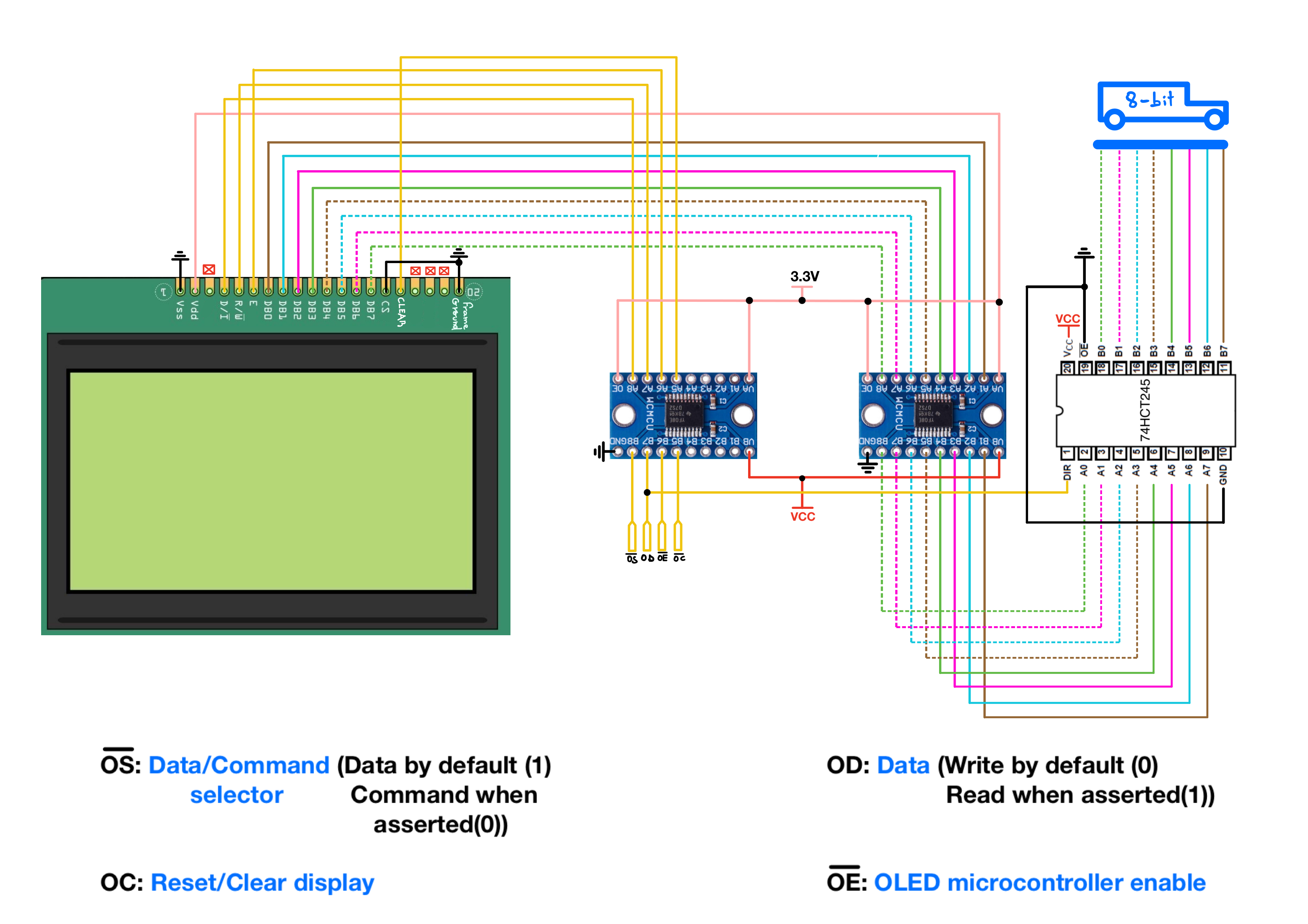
Control/Pins lines involved (10):
- |← Pin 4 - ~OS (data/command selector pin). A LOW on this line selects command writes, and a HIGH selects display data writes.
- |← Pin 5 - OD (read/write control pin). In my normal OLED write path, this line selects write mode.
- |← Pin 6 - OE (OLED enable/strobe pin).
- |←→ Pin 7 to 14 - D0-D7 (8-bit data bus pins).
- |← Pin 15 - CS (active-low chip select pin, tied to ground in this build).
- |← Pin 16 - OC (clear/reset pin).
OE is the OLED enable/strobe. During a write, OD selects write mode, ~OS selects whether the byte is interpreted as a command or display data, the CPU places the byte on D0-D7, and OE is pulsed to complete the transfer.
OD is also tied to the direction pin of the bus transceiver. Since the CPU mostly writes into the display, the transceiver usually points from the CPU data bus toward the OLED module. So the display may see the current bus value, but it does not treat that value as a completed transfer until the enable timing occurs.
Display Initialization
To understand how commands are sent to the display, let’s first go through the command format as described in the datasheet.
Command Format
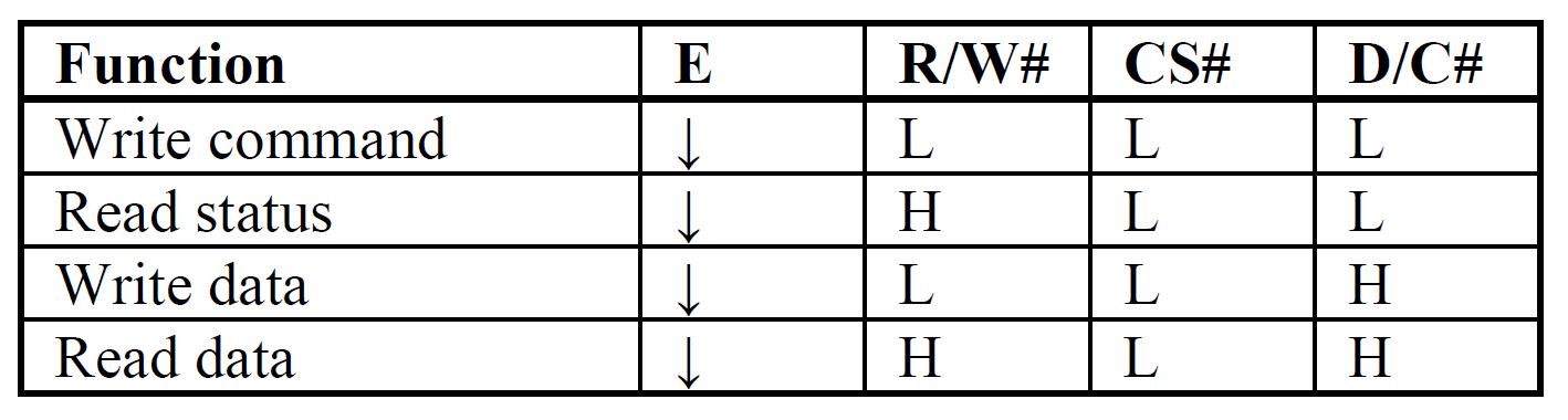
The OLED controller separates command writes from display-data writes using the data/command selector line.
On my CPU, that distinction is made through two OLED instructions:
OLC value   ; send value as an OLED command/control byte
OLD value   ; send value as OLED display data
OLC is used for controller commands and command parameters, such as setting the column window, row window, remap mode, contrast, or display state.
OLD is used when writing actual pixel data into GDDRAM.
For example, to set the column address window:
- Send
0x15withOLC. This is the SSD1325 command for setting the column address. - Send the start column, such as
0x00, withOLC. - Send the end column, such as
0x3F, withOLC.
After the row and column window are set, the CPU can send the GDDRAM write command and then stream pixel bytes through the data path. In that case, command/control bytes still use OLC, while pixel bytes use OLD.
CPU-Level OLED Instructions
The OLED hardware interface is controlled through a small set of CPU instructions:
OLR        ; reset / clear the OLED interface
OLC value  ; send value as a command/control byte
OLD value  ; send value as display data
OLC and OLD hide the low-level control-line sequencing from normal assembly programs. At the hardware level, the CPU still drives the 8-bit OLED data bus, selects command or data mode, and pulses the OLED enable line. At the assembly level, this becomes a simple distinction between command/control transfers and display-data transfers.
The higher-level OLED text and monitor code builds on top of these low-level instructions. This page focuses on the display hardware and initialization sequence.
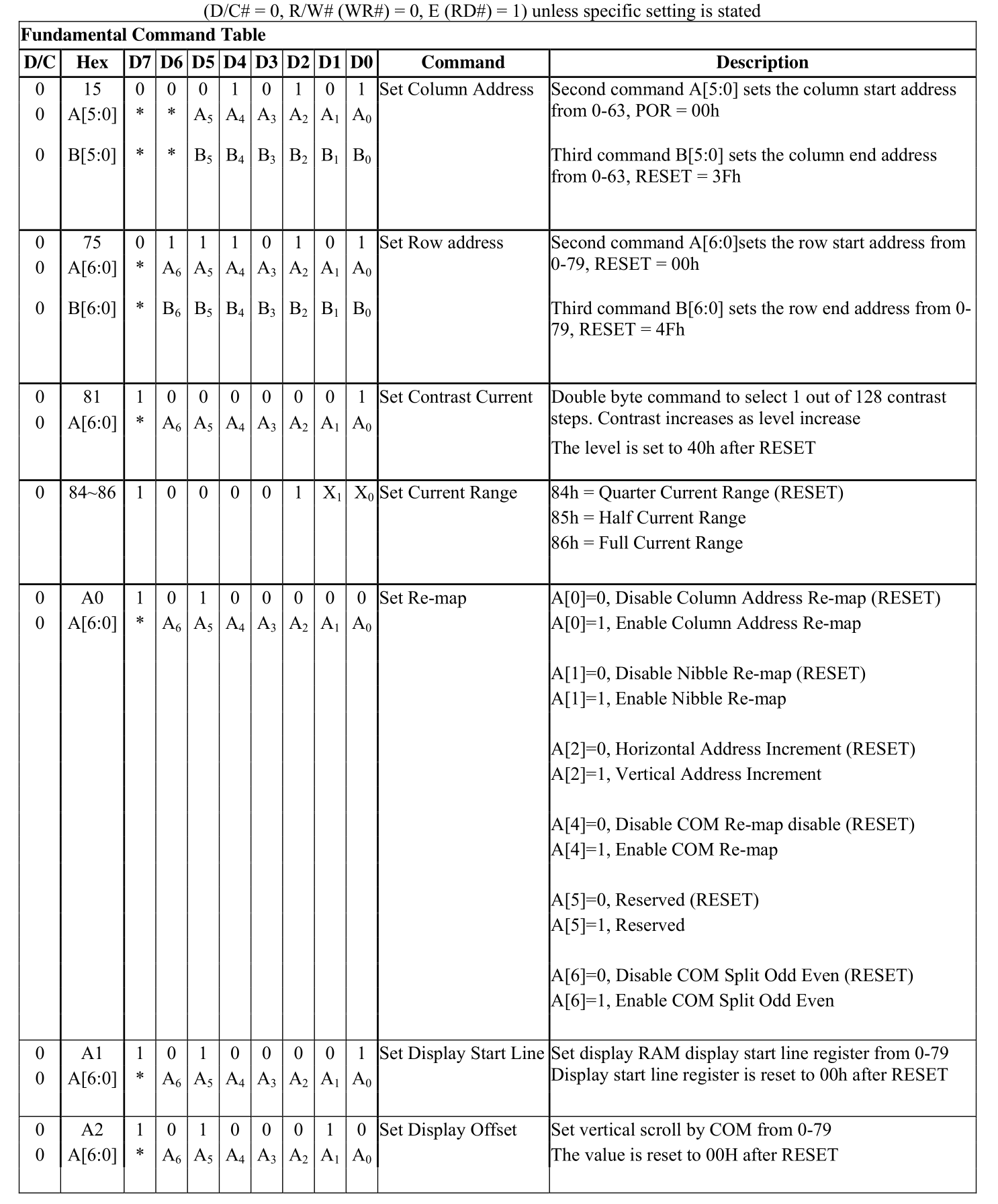
The rest of the table is included in the datasheet starting at page 31.
On page 6 of the SSD1325 datasheet:
“SSD1325 displays data directly from its internal 128x80x4 bits Graphic Display Data RAM (GDDRAM). Data/Commands are sent from general MCU through the hardware selectable 6800-/8080-series compatible Parallel Interface or Serial Peripheral Interface.“
This means that by default, the SSD1325 expects to interact with a 128x80 display. Since the display I use is a 128x64, the start and end GDDRAM addresses must be adjusted accordingly.
The SSD1325 uses 4-bit grayscale pixels, so each pixel is represented by one nibble. A single byte written to GDDRAM therefore contains two horizontal pixels. With the remap setting used in my current initialization sequence, the left pixel is stored in the high nibble and the right pixel is stored in the low nibble.
Because two pixels fit in one byte, a full 128x64 image occupies 64 bytes per row for 64 rows, or 4096 bytes total. This is why OLED drawing code has to think in packed pixel pairs rather than one byte per pixel.
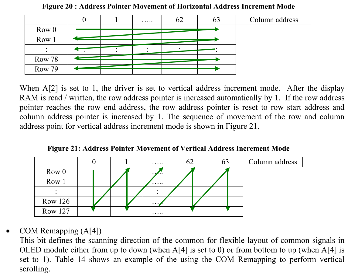
The datasheet also describes the “Set Re-map” command (A0h), which lets you configure the pointer position, as well as the orientation and progression of data within the display’s memory for standard top-left to bottom-right rendering of images and text. This is very handy for customizing the display to match specific writing/drawing requirements.
Initialization Sequence
The initialization sequence below, among many things, mainly clears any residual data, sets the display start line and offsets for correct image positioning, and finally, turns the display ON.
0- Hard Reset:
- Hold Reset line for a couple cycles.
1- Turn the Display OFF
- Send
10101110/0xAE
2- Set Column Address:
- Send
0b0010101/0x15(command to set column address). - Send
0b00000000/0x00(start column at 0). - Send
0b00111111/0x3F(end column at 63, which accounts for 128 pixels as each column consists of two pixels).
3- Set Row Address:
- Send
0b01110101/0x75(command to set row address). - Send
0b00000000/0x00(start from 0). - Send
0b00111111/0x3F(end row at 64).
4- Set Contrast Current:
- Send
0b10000001/0x81(command to set contrast). - Send
0b01111111/0x7F(specific contrast level).
5- Set Remap:
- Send
0b10100000/0xA0(command to set remap). - Send
0b01010010/0x52(specific remap settings to Increment pixel cursor from left to right and top to bottom).
6- Set Display Start Line:
- Send
0b10100001/0xA1(command to set start line). - Send
0b00000000/0x00(start line 0).
7- Set Display Offset:
- Send
0b10100010/0xA2(command to set display offset). - Send
0b01001011/0x4B(offset value 75).
8- Set Display Mode:
- Send
0b10100100/0xA4(A4(Totally OFF) A5(Totally ON)).
9- Set Full Current Range
- Send
0b10000110/0x86(Maximum current: Lowest divide ratio and highest oscillator frequency)
10- Set Clock Divide Ratio and clock frequency
- Send
0b10110011/0xB3 - Send
0b11110001/0xF1(Max Clock frequency)
11- Set MUX Ratio for highest frequency
- Send
0b10101000/0xA8 - Send
0b00111111/0x3F(1/64)
12- Set Gray Scale Table
Send
0b10111000/0xB8- Send
0b00000001/0x01 - Send
0b00010001/0x11 - Send
0b00100010/0x22 - Send
0b00110010/0x32 - Send
0b01000011/0x43 - Send
0b01010100/0x54 - Send
0b01100101/0x65 - Send
0b01110110/0x76
13- Draw filled black rectangle(Essentially clearing the display)
- Send
0b00100100/0x24 - Send
0b00000000/0x00 - Send
0b00000000/0x00 - Send
0b00111111/0x3F - Send
0b00111111/0x3F - Send
0b00000000/0x00
14- Turn the Display ON:
- Send
0b10101111/0xAF(command to turn on the display).
OLED row-boundary note: I found out that writes which touched raw pixel row 63 produced a visible artifact near the top of the OLED display. Normal 5x7 text usually hides this because the last row of each 8-pixel cell is blank spacing. Filled graphics can expose the behavior. For denser text and safer bottom-row behavior, I made a compact 4x6 text library that only uses raw rows 0 through 62.
ICs
1x Adafruit 2.7” Monochrome 128x64 OLED Graphic Display Module Kit (Adafruit, SSD1325 OLED driver’s datasheet)
2x TXS0108E 8-bit bidirectional level-shifter modules (Amazon, Datasheet)
1x 74HCT245, Octal Bus Transceivers With 3-State Outputs, (Digikey, Datasheet)
1x AMS1117-3.3 5V-to-3.3V regulator module (Amazon)