
 Clock
Clock
 Memory
 Control
ALU & Flags
Flags
My ALU has four flags: Zero (Z), Negative (N), Carry (C), and Overflow (O/V).
1. Arithmetic and Logic Operations
Zero (Z) Flag
The Z flag is set when the result of an operation is zero. It’s often used in control flow operations to make decisions based on the zero/non-zero outcome of previous operations.
Example:
0100 (4) - 0100 (4) = 0000 (0) sets the Z flag because the result is zero.
Negative (N) Flag
The N flag is set when the result of an operation, interpreted in two’s complement, is negative.
Example:
0001 (1) - 0100 (4) = 1111 (-3) in two’s complement sets the N flag as the result is negative.
Carry (C) Flag
The C flag changes during unsigned arithmetic to indicate a carry out of the most significant bit during addition, or a borrow during subtraction.
Example:
1111 (15) + 0001 (1) = 0000 (0) in unsigned arithmetic sets the C flag because there’s a carry out of the most significant bit.
Overflow (O/V) Flag
The O (or V) flag is set during signed arithmetic if the signed result falls outside the representable range for the given number of bits. In other words, the flag is set when adding two positive numbers produces a negative result, or when adding two negative numbers produces a positive result. The Overflow flag is not affected by or concerned with unsigned arithmetic.
Example:
0110 (6) + 0101 (5) = 1011 (-5)
1100 (-4) + 1011 (-5) = *1*0111 (7)
In signed arithmetic, these results set the O flag because the first result overflows the positive range, while the second overflows the negative range.
The CPU checks for overflow by comparing the carry into and out of the MSB. If they’re different, the O flag is set. The ALU internally uses a XOR operation on these two carry signals to set the O flag:
- If both are equal (either both are 0 or both are 1), there is no overflow, and the Overflow flag is not set.
- If they are different (one is 0 and the other is 1), there is an overflow, and the Overflow flag is set.
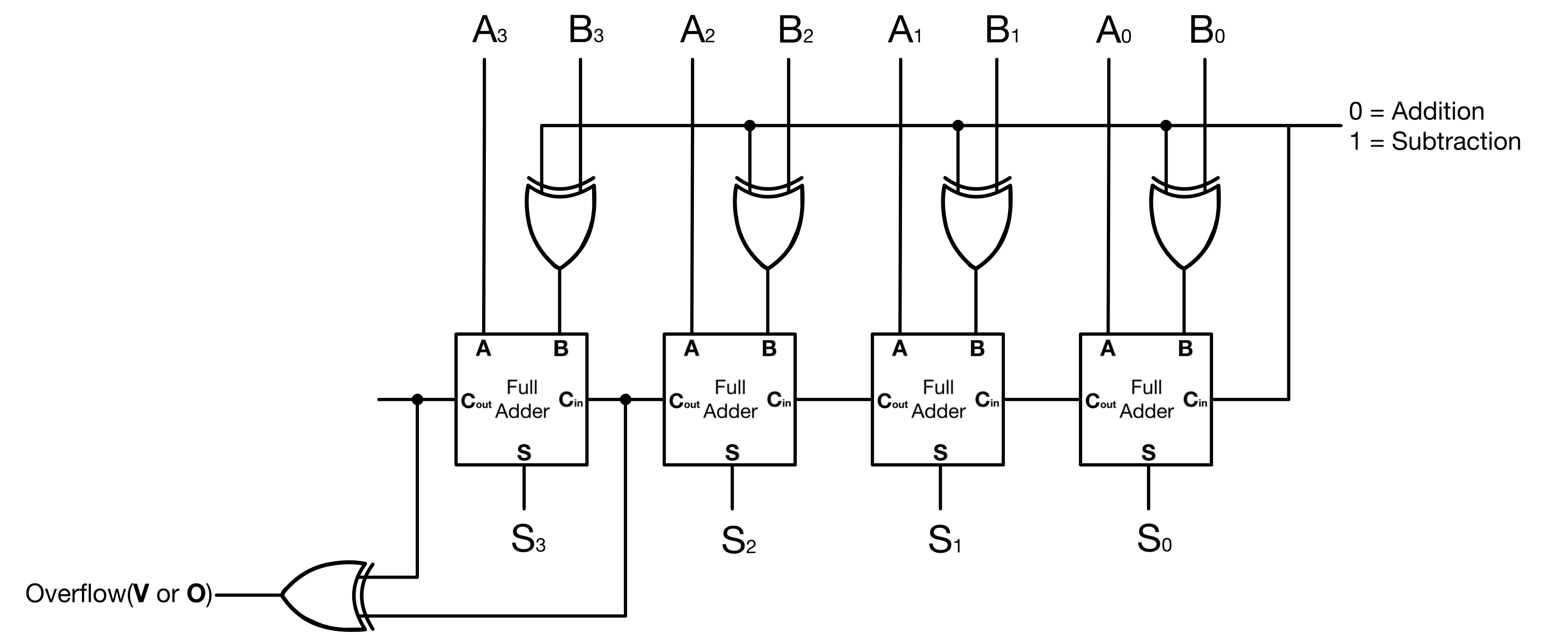
Examples:
 (4) +  (5) = (9)
0100 + 0101 = 1001  <-- ("4 + 5 = -7" in two's complements)

Carry      01000
Number A    0100
Number B  + 0101
            -----
            1001
(Carry out (0)) XOR (carry into MSB (1)) = 1 (Overflow flag is set)
(-4) + (-2) = (-6)
1100 + 1110 = 1010 <-- ("-4 - 2 = -6" in two's complements)

Carry      11000
Number A    1100
Number B  + 1110
            -----
            1010
(Carry out (1)) XOR (carry into MSB (1)) = 0 (Overflow flag is not set)
2. Shift Operations
Shift operations also influence the Z, N, and C flags.
Zero (Z) Flag in Shift Operations
- Example: Right shift
0001 (1)to0000 (0)sets the Z flag, which shows that the result is zero.
Negative (N) Flag in Shift Operations
- Example: Left shift
0100 (4)to1000 (-8)in two’s complement sets the N flag because the result is negative.
Carry (C) Flag in Shift Operations
The carry flag can be influenced during shift operations, especially during right shifts where the last bit shifted out is often stored in the carry flag.
Examples:
Right shift
1001 (9)to0100 (4)sets the C flag as the last bit shifted out is 1.
Together, the Z, O, N, and C flags provide a detailed post-operation status that can be used for efficient decision-making, error handling, and optimized control flow in various computational tasks.
Implementation
Control lines involved:
- |←~ZE Accumulator enable: Outputs accumulator’s content to 8-bit bus.
- |← ZS ALU select: 382 ALU or the Shift register.
- |← ZW Accumulator write
- |← Z0 ALU select_0
- |← Z1 ALU select_1
- |← Z2 ALU select_2
- |← HC_in Shift register’s carry-in: Replaces the shifted bit.
- |←~HC Shift register’s clear
- |←~FE Flags register’s enable: Flag register’s content enable to 8-bit bus
- |←~FW Flags register’s write
- |→ II Interrupt inhibit(Just uses a spare pin of flag register’s transceiver)(Comes from Interrupt logic and is not really related to the flags module)
The 74LS382 is the central chip of my ALU module. For reasons that I ignore, this chip is not available in the HC or HCT family. It performs the following arithmetic and logic operations: Addition, subtraction, OR, exclusive OR, and AND. Additionally, it can mirror its content and a null/zero output to the bus. It operates on 4-bit words, so just like the 74HCT173, I use a pair of it to do 8-bit operations.
| Pin No | Pin Name | Description |
|---|---|---|
| 1, 3, 19, 17 | A1, A0, A2, A3 | Word A inputs |
| 2, 4, 18, 16 | B1, B0, B2, B3 | Word B inputs |
| 5, 6, 7 | S0, S1, S2 | Function select inputs |
| 8, 9, 11, 12 | F0, F1, F2, F3 | Function output pins |
| 10 | GND | Ground |
| 13 | OVR | Two’s-complement overflow output |
| 14 | Cn+4 | Carry output to the next 4-bit stage |
| 15 | Cn | Carry input |
| 20 | VCC | Supply voltage |
Table 1: 74LS382 Pin Configuration
| S2 S1 S0 | Operation |
|---|---|
| 0 0 0 | ZERO/NULL |
| 0 0 1 | B minus A |
| 0 1 0 | A minus B |
| 0 1 1 | A plus B |
| 1 0 0 | A XOR B |
| 1 0 1 | A OR B (A+B) |
| 1 1 0 | A AND B (AB) |
| 1 1 1 | PRESET / all ones |
Table 2: 74LS382 Functions
To perform shift operations, I use a pair of 74HCT194s. It is a 4-bit bidirectional shift register with parallel and serial data input modes. It shifts data left or right and includes an asynchronous master reset.
| Pin No | Pin Name | Description |
|---|---|---|
| 1 | ~MR | Active-low asynchronous master reset |
| 2 | DSR | Serial data input for shift right |
| 3, 4, 5, 6 | D0, D1, D2, D3 | Parallel data inputs |
| 7 | DSL | Serial data input for shift left |
| 8 | GND | Ground |
| 9, 10 | S0, S1 | Mode select inputs |
| 11 | CP | Clock pulse input |
| 15, 14, 13, 12 | Q0, Q1, Q2, Q3 | Parallel outputs |
| 16 | VCC | Supply voltage |
Table 3: 74HCT194 Pin Configuration
For zero-detection, I use a 74HCT688 8-Bit Magnitude Comparator, which provides a cleaner and more efficient solution compared to using two separate ICs(a NOR and an AND IC) to make a zero detector
| Pin No | Pin Name | Description |
|---|---|---|
| 1 | E | Active-low enable input |
| 2, 4, 6, 8, 11, 13, 15, 17 | P0 to P7 | Word P inputs |
| 3, 5, 7, 9, 12, 14, 16, 18 | Q0 to Q7 | Word Q inputs |
| 10 | GND | Ground Pin |
| 19 | ~(P = Q) | Active Low Equal to output |
| 20 | VCC | Chip Supply Voltage |
Table 4: 74HCT688 Pin Configuration
Looking at the high level schematic/diagram below:
Let’s call the two 74LS382, the Arithmetic and Logic submodule (382), and the two 74HCT194, the shift submodule (194) or shift register. The accumulator/Z-reg (74HCT574) stores the ALU’s operation results.
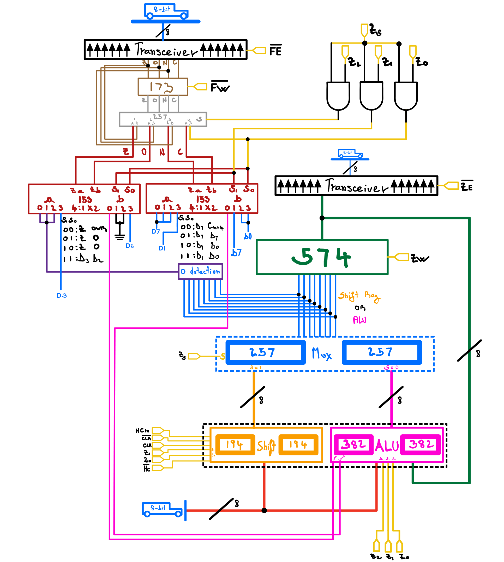
From the bottom up:
1- Both sub-modules receive their inputs from the data bus, with the 382 getting its second input/operand, from the accumulator. This means that to perform an operation between two operands, A and B; B must first be loaded into the accumulator.
2- The outputs of both sub-modules are directly connected to an 8-bit multiplexer made with two 74HCT257/257 4-bit muxs.
Note: While I use a 74HCT257, a 74HCT157 could also serve the purpose. The only difference between the two is that the 257 has a tri-state output, which I am not using.
The ZS control lines determine which sub-module’s value gets selected by the multiplexer. ZS = 0 selects the Arithmetic and Logic sub-module and ZS = 1 selects the shift sub-module.
3- The output from the sub-modules mux is connected directly to both the accumulator and the zero-detector. The transceiver between the accumulator’s output and the bus, much like most transceivers in this build, lets the content of the accumulator be displayed on status LEDs without interfering with the bus content.
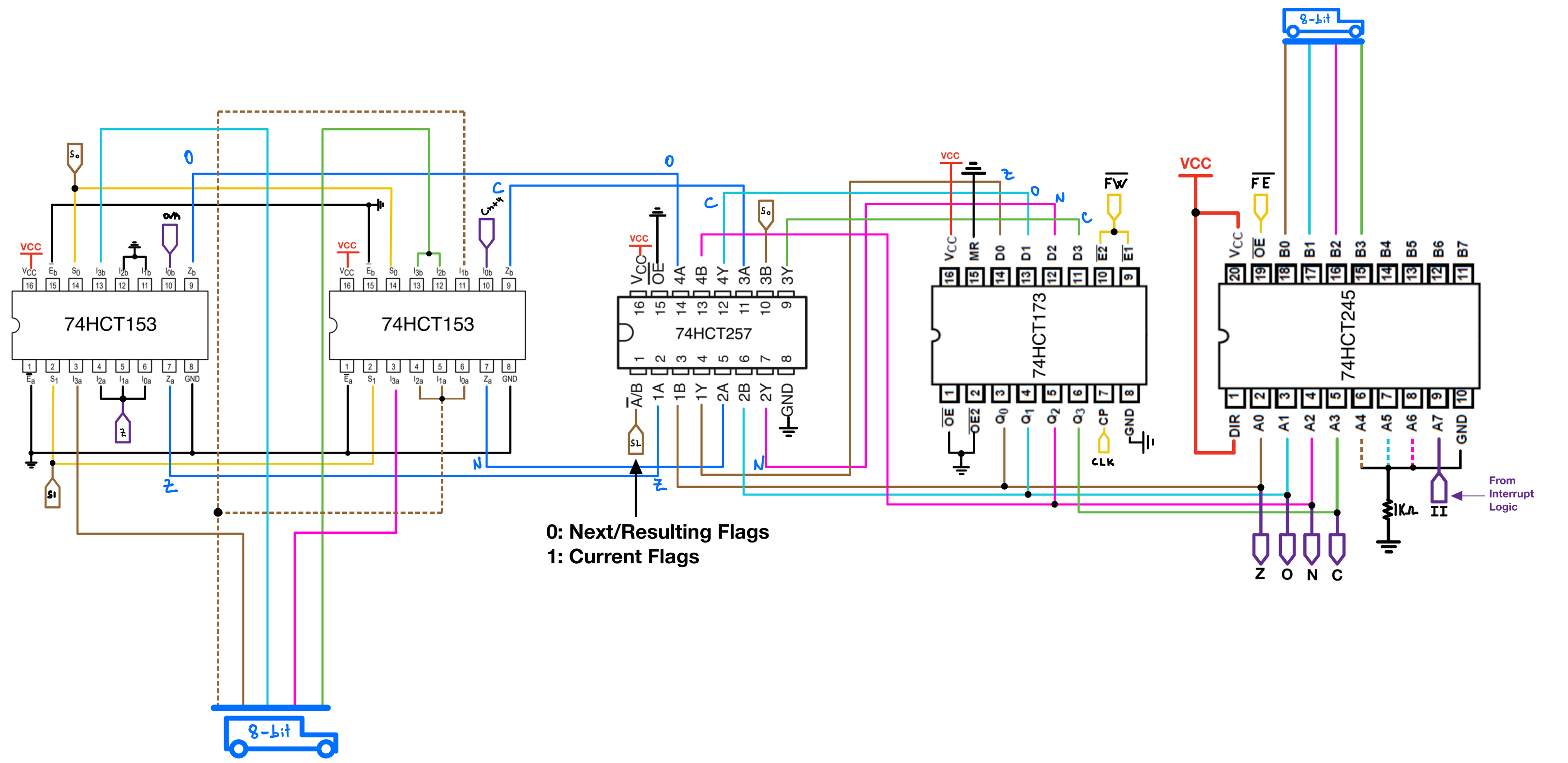
The two 74HCT153 multiplexers(flags mux) are used to select the appropriate flag based on the current operation. The output from the flags mux is then fed into a final 74HCT257 before entering the flags register. The selector can either overwrite the flag register’s contents or preserve the previous flags.
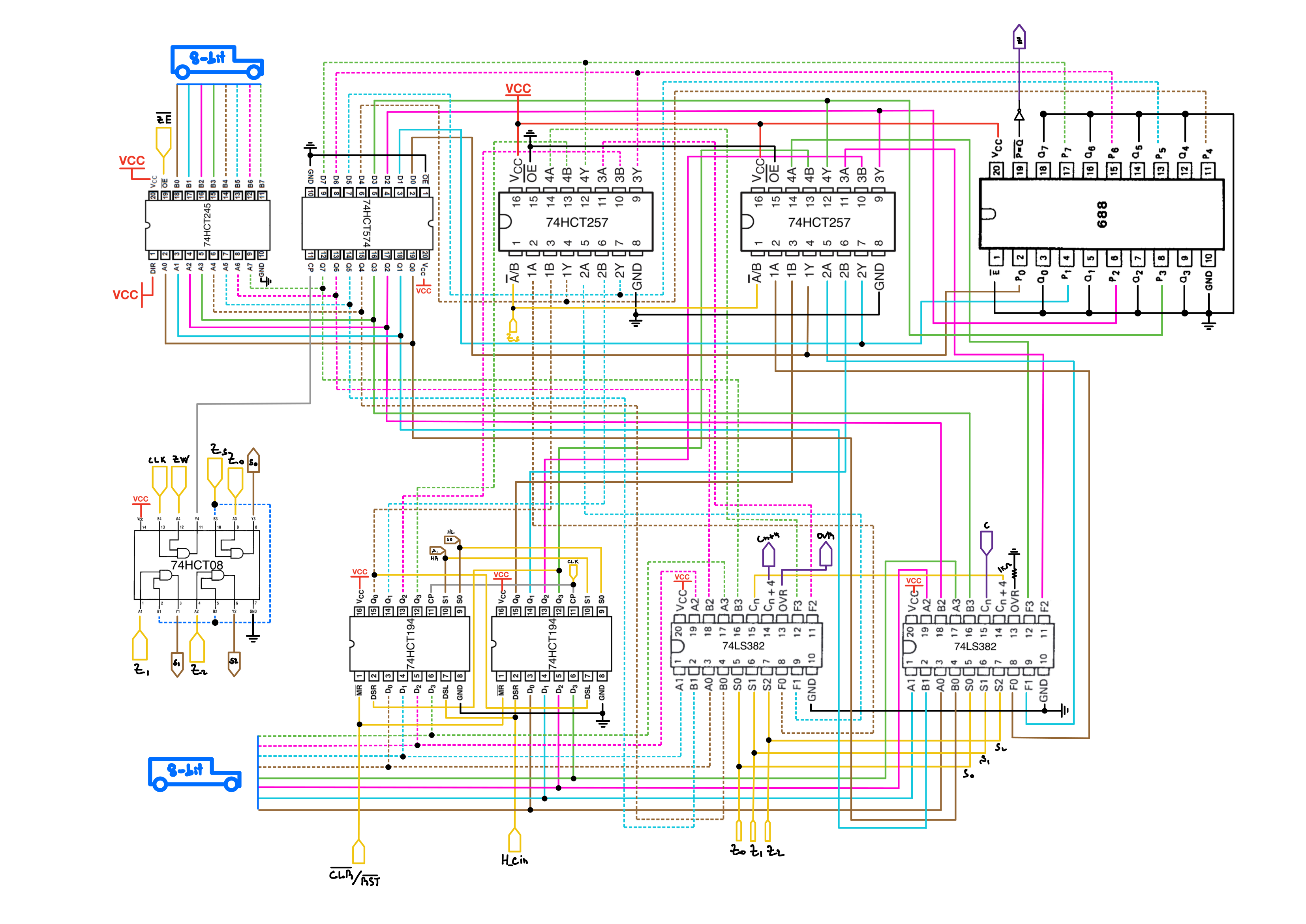
The two figures below show the full schematic of the ALU module:
| Zs | Z2 | Z1 | Z0 | Accumulator’s input | Z flag | O/V flag | N flag | C flag |
|---|---|---|---|---|---|---|---|---|
| 0 | 0 | 0 | 0 | 0x00 | Z | OVR | D7 | Cn+4 |
| 0 | 0 | 0 | 1 | B - A | Z | OVR | D7 | Cn+4 |
| 0 | 0 | 1 | 0 | A - B | Z | OVR | D7 | Cn+4 |
| 0 | 0 | 1 | 1 | A + B | Z | OVR | D7 | Cn+4 |
| 0 | 1 | 0 | 0 | A XOR B | Z | OVR | D7 | Cn+4 |
| 0 | 1 | 0 | 1 | A OR B | Z | OVR | D7 | Cn+4 |
| 0 | 1 | 1 | 0 | A AND B | Z | OVR | D7 | Cn+4 |
| 0 | 1 | 1 | 1 | 0XFF | Z | OVR | D7 | Cn+4 |
| 1 | 0 | 0 | 0 | 194 | Z | OVR | D7 | Cn+4 |
| 1 | 0 | 0 | 1 | LSL | Z | 0 | D7 | D7 |
| 1 | 0 | 1 | 0 | LSR | Z | 0 | D7 | D0 |
| 1 | 0 | 1 | 1 | Bus | D3 | D2 | D1 | D0 |
| 1 | 1 | 0 | 0 | Reset Carry | Z | O/V | N | 0 |
| 1 | 1 | 0 | 1 | Set Carry | Z | O/V | N | 1 |
Table 5: ALU’s Truth Table
Important Microcode-Related Notes
Mirroring Bus Content
Note that the 74LS382 does not have a “mirror bus” function; which would have made loading the accumulator with the value on the bus very straightforward. The 74HCT194 on the other hand does have this function; but since it is a sequential component, it requires an extra cycle to be loaded before its output can be loaded into the accumulator.
Flags And Shift Register Control Contention
Writing the bus content to the flags register requires Zs = Z1 = Z0 = 1. That configuration sets the shift register to also receive the bus content. In other words, every time the CPU writes bus content to the flags register, it also writes to the shift register. Besides the soft reset instruction, I do not have any instruction that uses both FLG_MIRROR_BUS and a shift operation right now.
ADD, SUB, and CMP
The ALU’s carry-in is permanently connected to the carry flag from the previous operation. Because of that, arithmetic instructions depend on the current carry state unless the carry flag is set or cleared explicitly.
For addition, the carry flag serves as a normal carry-in. If $A contains 0b11111111, then ADD $A, 0b1 sets the C flag. If another ADD immediately follows while C is still set, the ALU includes that carry in the next addition. In that sense, ADD behaves like ADC unless I clear the carry flag first.
So an ordinary ADD $A, 1 should be written as:
CLC
ADD $A, 1
For subtraction and compare, the carry flag behaves as a no-borrow input. A carry value of 1 means no borrow, while a carry value of 0 means a borrow is included. Because of that, ordinary subtraction and compare operations should start with STC.
So an ordinary SUB $A, 1 should be written as:
STC
SUB $A, 1
And an ordinary CMP $A, 1 should be written as:
STC
CMP $A, 1
After a subtraction or compare, C = 1 means no borrow occurred, and C = 0 means a borrow occurred.
ICs
2 x 74LS382(Datasheet)
2x 74HCT194 (Digikey, Datasheet)
4x 74HCT257 Quarduple 2:1 mux (Digikey, Datasheet)
2x 74LS153 (Dual 4- to 1-Line Selector/Multiplexer), (Digikey, Datasheet).
1x 74HCT688 8-Bit Magnitude Comparator, (Jameco, Datasheet).
2x 74HCT245, Octal Bus Transceivers With 3-State Outputs, (Digikey, Datasheet).
1x 74HCT173, 4-Bit D-type Registers with tri-state Outputs, (Digikey, Datasheet).
1x 74HCT08 Quadruple 2-Input Positive-AND Gates 74HCT08 (Digikey, Datasheet)