Nomenclatures & Notes
Most Posts start with a “Basics Primer” section containing a high-level and basic description of the module being discussed.
Whenever I mention SAP-1, it specifically refers to Ben Eater’s build, unless stated otherwise.
I use the terms “CPU”, “build”, and “computer” interchangeably. This is a deliberate choice for clarity and ease of understanding.
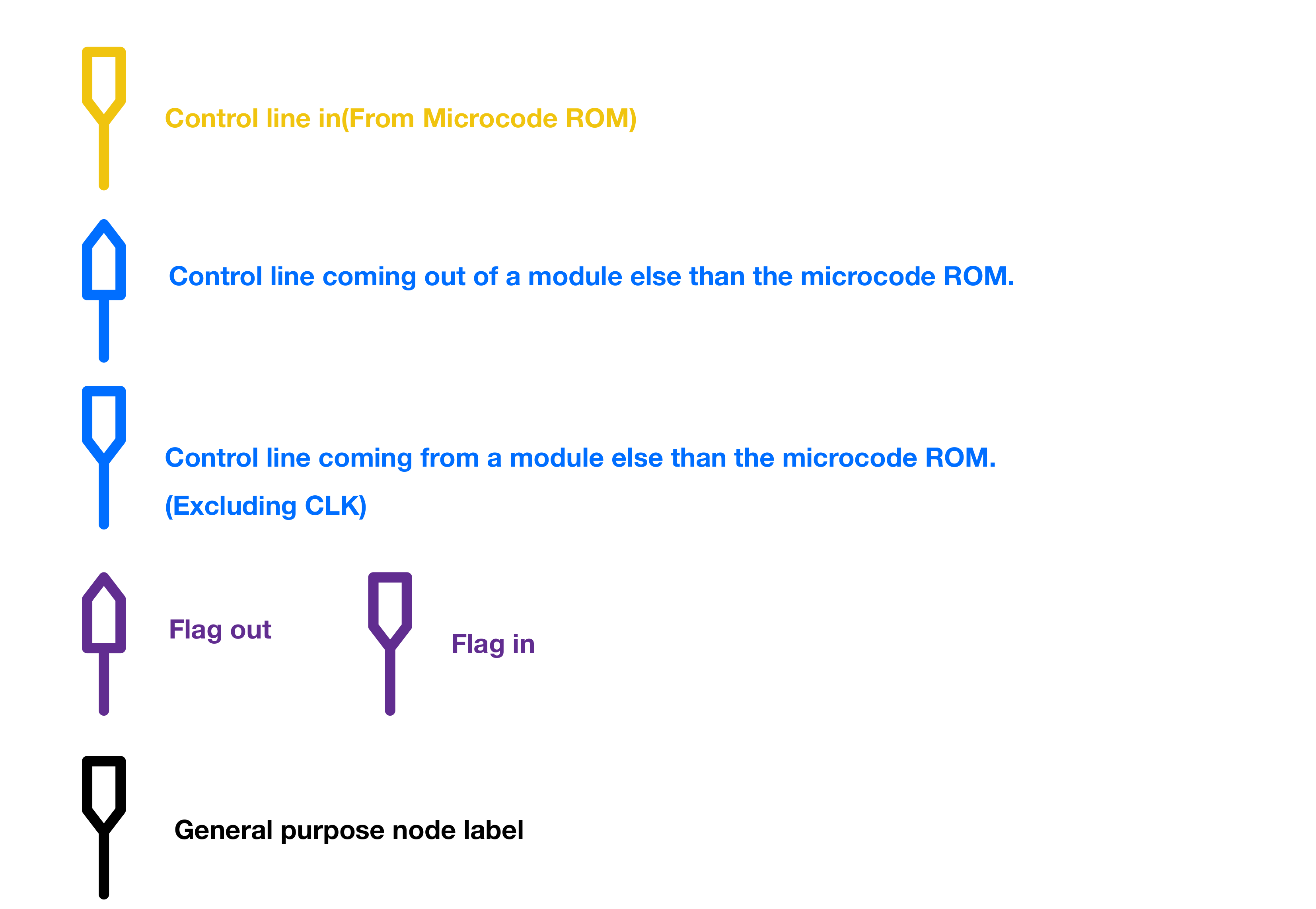
|← and |→ are used to specify whether a control signal is an input or an output to a module, respectively.
~ Denotes active low control lines.
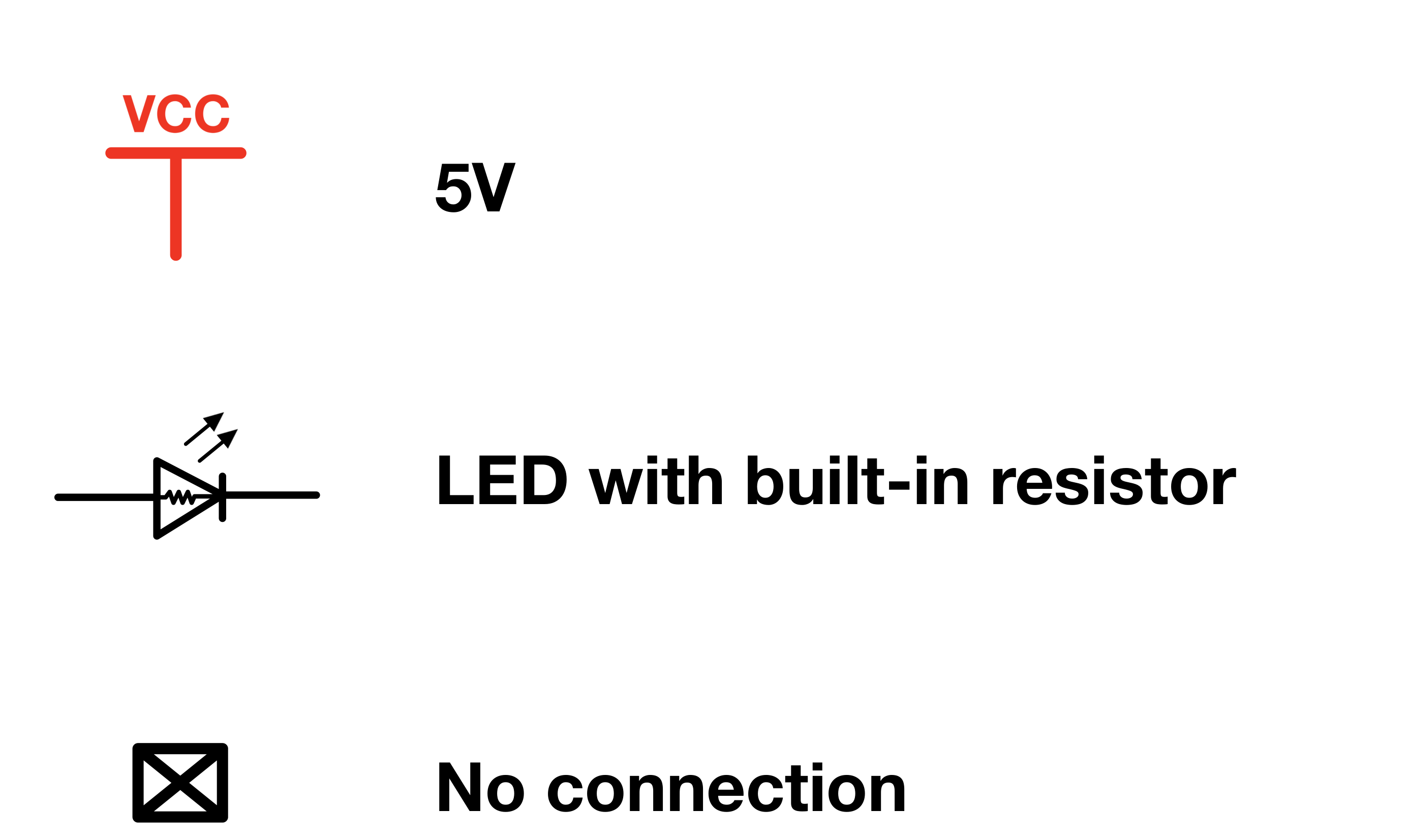
I use HIGH, ON and 1 interchangeably, as well as LOW, OFF and 0.
I made all the schematics for this project using a top-notch, industry-tier, color-coded, super professional EDA software called Notability.
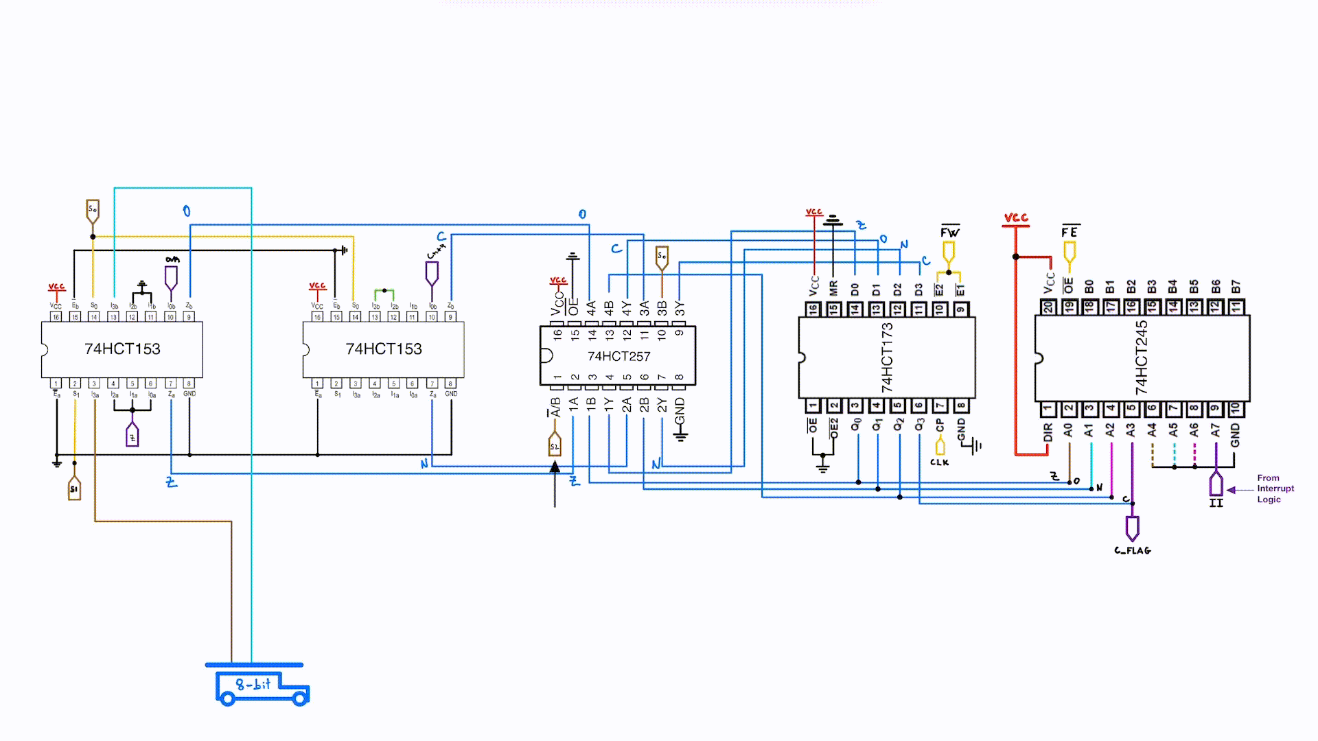
On a serious note, Notability is a note taking app I’ve been using extensively throughout my college years. Most of the schematics and diagrams that I made myself(All figures without cited sources) in this series of posts, were made using Notability. Being able to freely draw the schematics helped me have control on the ICs orientations on the breadboards, which was very important to minimize the area used. You’ll notice throughout the posts that I mostly use the actual chips pinouts instead of logic/schematic symbols, because it makes it very easy to transfer the final schematics over the breadboards.
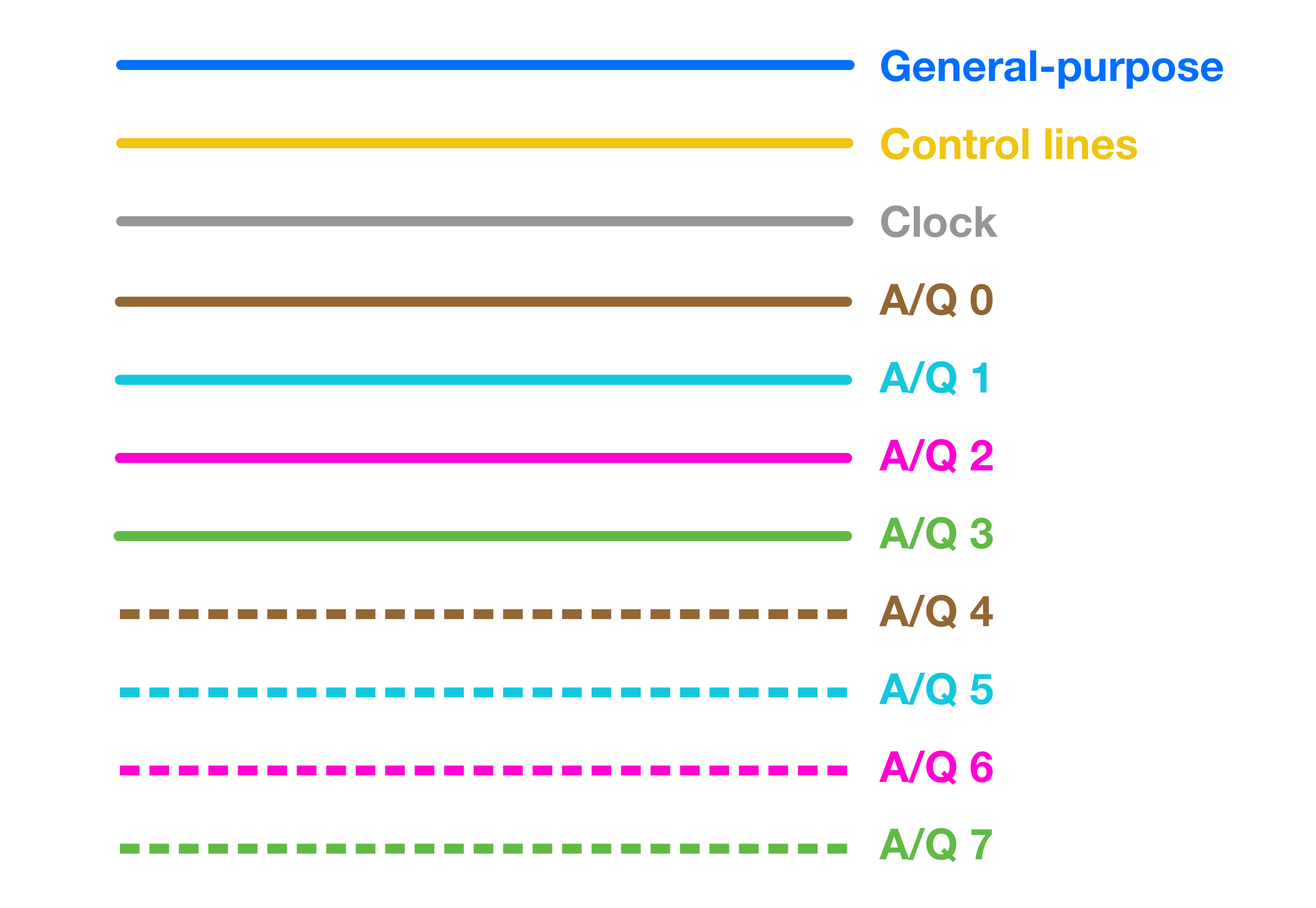
- I’ve applied a straightforward color-coding system to the data lines in the schematics to indicate their bit significance. The coding starts with solid brown for the least significant bit (bit 0) and progresses through to dotted green for the most significant bit (bit 7). Each bit is represented by a unique color, with solid lines for the lower four bits and dotted lines for the higher four. For instance, bit 0 is linked with solid brown, bit 2 with solid purple, bit 5 with dotted light-blue, and so on. On components that use more than 8 bits the same color coding rolls over at the 9th bit, and so forth.
The data and address bus notation that I’ve used for this project’s schematics is the the drawing of an actual bus. Why? Because it makes sense!

«««««««««« Previous Post: Overview
Next Post: Basic Definitions And References »»»»»»»»»»
Updated: